Alex Munro · Engineering portfolio
I design aircraft, analyze structures and build competition robots.
Each project shows the problem, my role and the process. Predictions are labeled as predictions, and anything not built yet says so.
Projects
Tracer speed wing
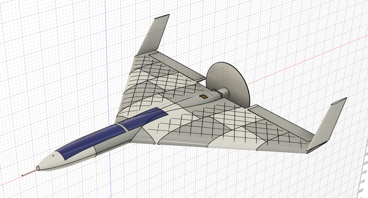
A 3D-printed FPV flying wing designed for 100 mph on 4S, with its speed predicted before the first flight. CAD complete; build next.
FTC Team 11588 Carpe Diem
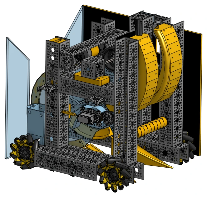
Three seasons on a FIRST Tech Challenge team, from builder to build captain and co-captain. I've built the drivebase every season. In 2025–26 the team won the Inspire Award and competed at the NC Championship.
Wing truss study
Verified a cantilever wing truss with two independent solvers, then cut its modeled mass by 31.9% for 3.6% more tip deflection.
Viper 5-inch FPV quad
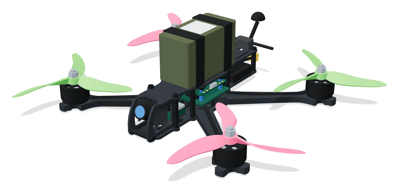
A beginner-friendly, upgradeable 5-inch quad for learning to build and fly. Parts selected under a $500 aircraft budget; build next.
Planned
Vanguard tiltrotor UAV. A two-rotor tiltrotor VTOL that takes off and lands vertically, meant to carry 5–7.5 lb (2.3–3.4 kg). I took it through several CAD revisions in 2026 and scoped a thrust and tilt test stand for its motors. It's on hold until I have the time and budget to do it properly. Tracer comes first, and it builds the printing, flight-control and testing experience Vanguard will need.
About
I learn by building: model the part, make it, then find out what I got wrong. On the FTC robots that meant a claw that kept breaking until I redesigned it, and slide rigging that went from string to Kevlar to steel cable. The projects here are the ones where I can show the reasoning, not just the result.
My focus is mechanical and aerospace engineering, especially flight vehicles. I'm designing a 3D-printed speed wing and planning a 5-inch FPV quad to learn on, with a tiltrotor VTOL planned after that. I'm also Build Captain and Co-Captain of an FTC robotics team, and I completed a structures research project with NC State in summer 2026.
Skills
- CAD
- Onshape (intermediate); working knowledge of Fusion 360, including Python-scripted CAD
- Analysis
- Finite element analysis (CalculiX), structural truss analysis, gear-ratio and mass-and-balance calculations
- Mechanical
- Mecanum drivetrains, linear slides and cable rigging, ball intakes and belt conveyors, indexing and paddle transfers, launchers and turrets, claws, camera pan-and-tilt mounts
- Fabrication
- FDM 3D printing, CO2 laser cutting, soldering, mechanical assembly with aluminum structural parts, bearings and fasteners
- Software
- Python, Excel
- Documentation
- Bills of materials, build logs, technical training guides
Contact
Questions about any of these projects are welcome.
Aircraft design · Solo project · Since September 2026
Tracer, a 3D-printed speed wing
A small FPV flying wing designed to fly 100 mph on a 4-cell battery, printed in 25 parts that fit a 220 mm printer bed. The design is finished and its speed is predicted, not yet measured. The first flights are the test.
- Role
- Solo, self-directed
- Started
- September 2026
- Status
- CAD complete (V1.2.1); parts not yet printed
- Tools
- Fusion 360, Python (AeroSandbox), ArduPilot simulator
The goal
Tracer is my main project: a small, fast aircraft I can design, print and fly myself. It also builds the flight software (ArduPilot), printing and test experience that a larger aircraft like my planned tiltrotor will need.
The target is a measured number: at least 100 mph of airspeed on a 4-cell (4S) battery, averaged over passes in both directions to cancel the wind. A pitot-tube airspeed sensor measures it, because GPS ground speed can't separate drag from wind.
Why a tailless delta
Research for the project recommended a conventional pusher with a V-tail. I chose a tailless delta instead, because it is more focused on speed.
- Less drag: no tail and less wetted area.
- Stiffness: a short span with a deep 19.3 in (490 mm) root chord resists flutter, which matters because foamed printed plastic is soft.
- Fewer servos: two elevons do the work of separate ailerons and elevators.
- The cost: a tailless wing is sensitive to its balance point and needs twist to trim itself, so the stability analysis came before the detailed CAD.
Design
| Span | 31.5 in (800 mm) |
| Root / tip chord | 19.3 in (490 mm) / 3.5 in (90 mm) |
| Planform | 45° leading-edge sweep, straight trailing edge |
| Wing area | 360 in² (23.2 dm²), aspect ratio 2.76 |
| Airfoil | MH 45 with 3° washout |
| Wing loading | 13.5 oz/ft² (41.1 g/dm²) at the estimated weight |
| Propulsion | 2814 1250KV motor, APC 8x8 pusher prop, 4S 2,200 mAh battery |
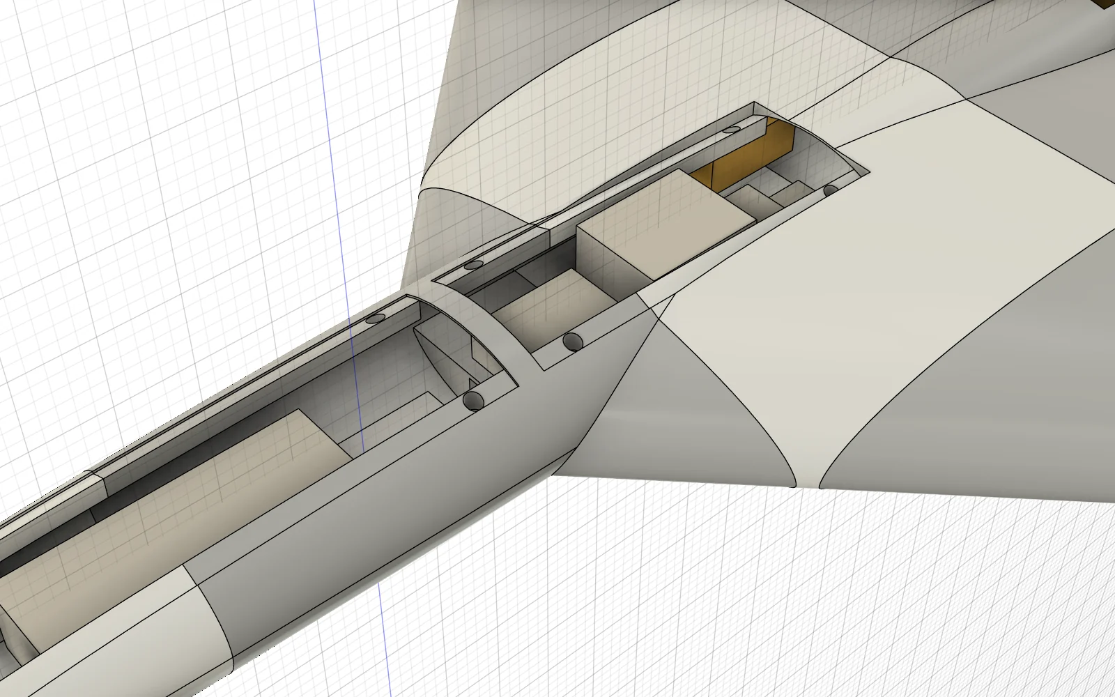
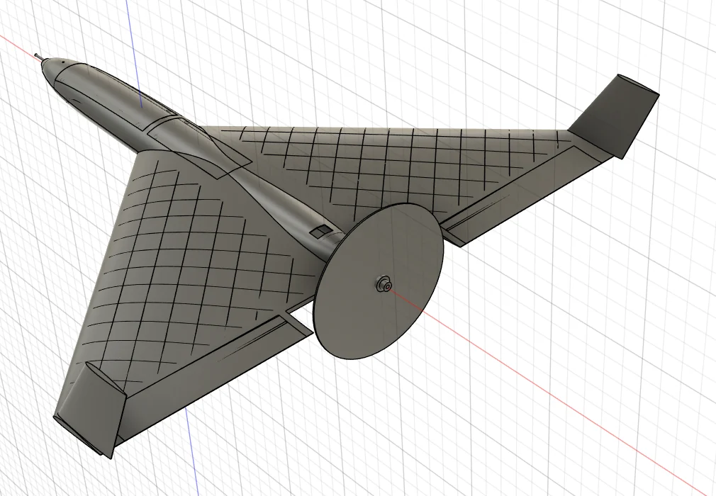
The airframe is 25 printed parts: a four-piece center body, three spanwise sections per wing, elevons, tip fins and removable hatches held by magnets. The parts key together with 3 mm carbon pins, and carbon tube spars run through the wing.
The skins are foamed lightweight PLA printed one line thick with no infill. Narrow 0.15 mm slots in the model print as internal webs, so the wing gets ribs without separate rib parts. Load-bearing points, the spar sockets and the motor mount, are PETG.
Key design decisions
Motor: 1250KV instead of 1400KV
The APC 8x8 propeller is rated to 18,750 rpm. The motor and prop model predicted the 1400KV motor would spin it to 19,200–19,600 rpm on a fully charged pack. In the same case the 1250KV motor stays under the limit at about 17,750–18,050 rpm and is still predicted to clear 100 mph.
Twist and fins
A tailless wing trims itself with washout, a twist that lowers the angle of the tips. With 2°, the elevons would sit neutral only at about 142 mph, faster than the plane can fly. At 3° that drops to about 97 mph, so the wing flies near neutral at speed. The same analysis showed weak directional stability with the first tip fins (Cnβ 0.024 per radian). Taller 4.9 in (125 mm) fins raise it to about 0.055.
Balance point
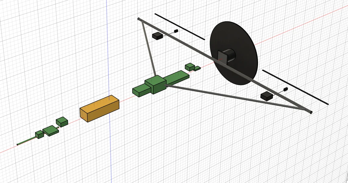
Two methods put the neutral point 250–261 mm behind the wing's apex. The balance point is set at 208 mm, a 12.5–15.8% static margin, with 205 mm for the first flight and 215 mm as the aft limit. The battery slides on its tray to set it. With the battery fully forward, the model balances at 204.7 mm.
Built to be serviced
V1.2 glued a plywood firewall in place, but the motor bolts on from its base, so that firewall would have trapped the motor inside the body. V1.2.1 replaced it with a bolt-in PETG motor plug held by two screws, so the motor comes out the back. A new top hatch reaches the speed controller after the body is glued.
Spars that go in last
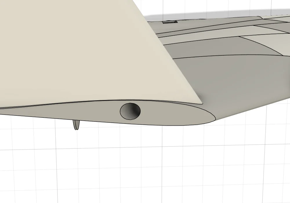
The rear spar runs straight across the span and the front spars run diagonally, so no wing section can slide on with both in place. The front-spar holes run out through the wing tips, and the front spars go in last from there.
Predictions, written before flight
These come from low-order models (AeroSandbox, plus a motor and prop model built on APC's published propeller data). They are written down before the first flight so the flight data can test them.
| Metric | Prediction |
|---|---|
| Top speed, mid-charge pack | 109–117 mph |
| Top speed, fresh pack | 116–125 mph |
| Static thrust | 5.2 lb (2,370 gf) at 15.2 V |
| Stall speed | About 23 mph |
| Static margin at 208 mm | 12.5–15.8% |
| Cruise at 60 mph | About 13 minutes on one pack (rough) |
Speed ranges cover three drag assumptions (CD0 0.018 to 0.025). The speed model uses a conservative 1.10 kg (2.43 lb) all-up weight.
Checked in the simulator
The flight controller settings (ArduPlane 4.7.1) were run in ArduPilot's simulator with a generic flying wing before any hardware was bought. That checks the settings, not how Tracer flies. Hand launch, mode switching, failsafes and geofences all passed, and the run caught two problems:
- A safety-check parameter had been renamed in version 4.7, so the old name would have failed to load.
- If the battery dropped straight to its critical level, the plane would only have warned instead of flying home. Both battery levels now trigger return to launch.
Status and next steps
The result that matters is the comparison: measured speed, current and balance point against the predictions above.
Credits: I chose the tailless delta layout and directed the design. Claude (Anthropic) wrote the Python scripts that generate the Fusion 360 CAD, the aerodynamic and propulsion models, and the simulator tests.
FPV quadcopter · Solo build · Since September 2026
Viper, a 5-inch FPV quadcopter
A beginner-friendly, upgradeable 5-inch FPV quad on a TBS Source One V6 frame, for learning to build and fly. The parts are selected and a fit-check CAD assembly is done. It isn't built yet.
- Role
- Solo, self-directed
- Started
- September 2026
- Status
- Parts selected; fit-check CAD; not yet built
- Budget
- $500 for the aircraft; $415.43 selected
The goal
Viper is the aircraft I learn on: building, soldering, setting up and flying. The requirements:
- Beginner-friendly but good quality, and easy to upgrade later.
- Made for cruising, exploring and learning to fly something I built myself.
- $500 or less for the aircraft alone. The radio, goggles, charger and batteries are budgeted separately.
- Digital video from a non-DJI system, because of support and supply concerns.
- Parts from major retailers, plus a local hobby shop.
Parts
| Part | Selection | USD |
|---|---|---|
| Frame | TBS Source One V6, 5-inch | 42.00 |
| Flight controller and ESC | SpeedyBee F405 V4 + BLS 55A stack | 69.99 |
| Motors | 4 × EMAX ECO II 2306 1700KV | 63.96 |
| Video | Walksnail Avatar HD Pro, 32 GB | 165.99 |
| Receiver | RadioMaster RP1 V2 ExpressLRS | 30.00 |
| Propellers | HQProp Ethix S3, 5 × 3.1 × 3 | 4.00 |
| Lost-drone finder | VIFLY Finder 2 | 19.49 |
| Hardware | Assembly hardware allowance | 20.00 |
| Total | 415.43 |
Prices recorded September 17, 2026. Selected, not yet purchased.
Key decisions
Frame: TBS Source One V6
An established, repairable carbon frame with replaceable arms. It takes both 20 mm and 30.5 mm electronics stacks, which leaves room to upgrade the electronics later.
Splitting the aircraft from the ground gear
The first plan priced everything at once: the aircraft, radio, goggles, charger, batteries and tools. Against a target of about $1,500, it came out at $1,682.18 delivered. Budgeting the aircraft on its own, at $500 or less, made the decisions clearer.
A cheaper flight stack
The first plan used a Skystars F7 stack at $126.99. The revision moved to the SpeedyBee F405 V4 stack at $69.99, which is $57 less and helps keep the aircraft under $500. It can also run ArduPilot, the autopilot software Tracer uses.
Weight
I asked whether a 5-inch could get under 250 g (0.55 lb). The planning estimate for this kind of build is about 600 g (1.32 lb) ready to fly, so Viper stays a normal 5-inch and the real weight gets measured once it's built.
Fit-check CAD
The assembly takes the frame plates and mounting holes from TBS's published drawings and the electronics from published dimensions. The battery (a 6S 1,300 mAh placeholder), wiring, motor details and propellers are estimates. It checks that everything fits; it isn't manufacturing CAD.
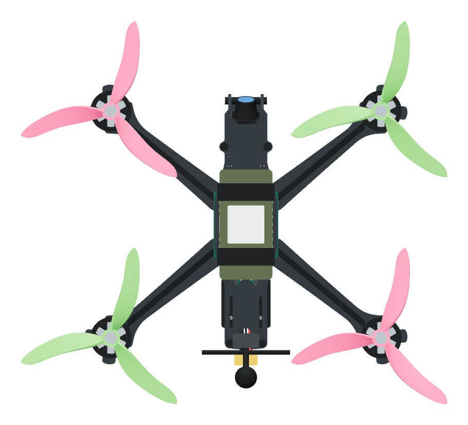
Build and first-flight plan
- Simulator first: 10–20 hours in Liftoff with the real radio, practicing takeoff, turns, returning, landing and disarming, then acro.
- Dry-fit, then solder: fit the stack, camera and video transmitter before cutting any wire; practice on a spare board, then solder the motors, power lead and capacitor, receiver, video and finder.
- First power and setup: power up through a smoke stopper, back up the factory configuration, then set the motor layout, receiver, on-screen display, arming, beginner rates and battery monitoring.
- Props-off checks: motor order and direction, attitude, arming, and a link-loss failsafe that drops and disarms.
- First flights: a short hover with a visual observer, then short circuits. Record weight, battery used and flight time as the baseline.
Planning estimate: 12–20 hours of assembly and setup, 10–20 hours in the simulator and 2–4 hours of field checks.
Status and next steps
Credits: the parts research, build plan and fit-check CAD on this page were produced with ChatGPT (OpenAI), working from my requirements.
Structural analysis · NC State GTI Research Academy · Summer 2026
A wing truss 31.9% lighter for 3.6% more deflection
A cantilevered wing truss had to get lighter without getting noticeably less stiff. I modeled it in CAD, confirmed its tip deflection with two independent solvers after the required simulator failed, and removed 36 of its 106 members while keeping deflection within 5%.
- Role
- Student researcher, individual project
- Mentor
- Dr. Liming Xiong, NC State Mechanical & Aerospace Engineering
- Timeline
- June 29 – August 7, 2026
- Outcome
- Pass, with a certificate and faculty evaluation
- Tools
- Onshape, Python, CalculiX
The problem
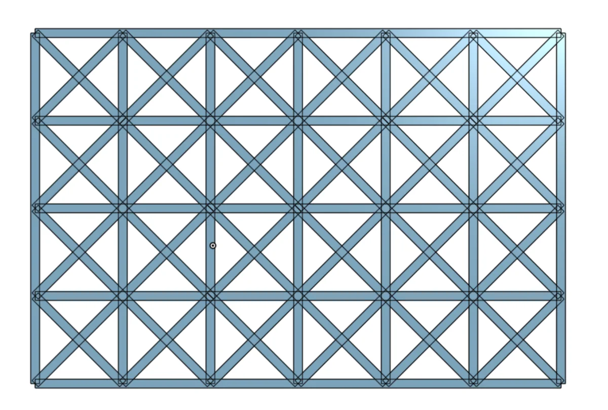
The structure is a cantilevered wing truss: a 7 × 5 grid of joints at 1 m (3.28 ft) spacing, with every bay X-braced. That gives 35 joints and 106 members over 6 m × 4 m (19.7 × 13.1 ft). The five joints along the root are pinned to the fuselage, and a 10,000 N (2,248 lbf) load hangs from the tip joint at mid-height. Every member is aluminum (E = 69 GPa) with a 100 cm² (15.5 in²) cross-section.
There were two questions. How far does the tip move? And how many members can be removed before it moves more than 5% further?
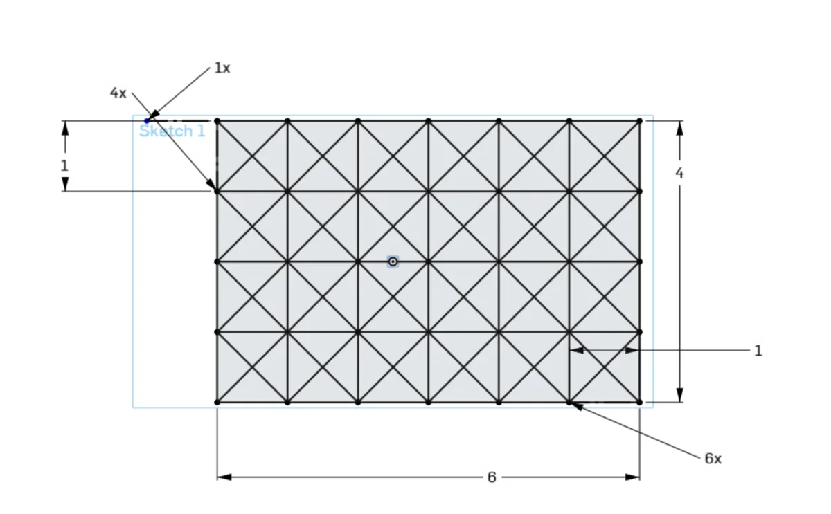
Process
Getting the geometry out of CAD
Onshape won't export sketch lines as STEP. I converted the sketch into a 3D wireframe with Composite Curve in Approximate mode at degree 1. A degree-1 fit is exact for straight lines, and it handles joints where up to eight members meet.
When the simulator failed
The assignment called for SimScale. On import, the STEP file split into 39 disconnected bodies, and SimScale tied them together with contact conditions instead of shared nodes. That lets the joints move relative to each other, which is the wrong physics for a pin-jointed truss. Imprint and merge did not fully fix the geometry.
Rather than report a number from a model I knew was wrong, I solved the structure two independent ways and documented the substitution in the report.
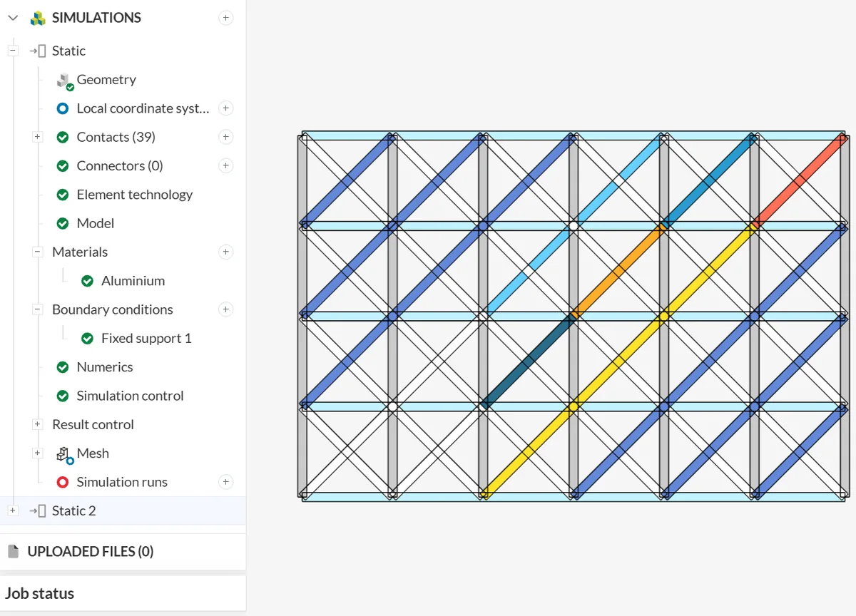
Two solvers, one answer
The first solver is a Python implementation of the direct stiffness method. The second is CalculiX, an open-source finite element solver, using truss elements that carry axial force only. Both treat every joint as a pin.
| Method | Vertical tip deflection | Horizontal |
|---|---|---|
| Python, direct stiffness | −0.1188 mm | ≈ 0 |
| CalculiX, truss elements | −0.11875 mm | ≈ 0 |
Horizontal movement is effectively zero in both, as expected: the load sits on the truss's horizontal centerline. An early run gave −0.1216 mm because the load joint's row index was off; correcting it to match the CAD coordinate, (6 m, 2 m) from the bottom-left corner, gave the final value.
Removing members
The reduction is a greedy search:
- Solve the structure and rank every member by the magnitude of its axial force.
- Try removing members from lowest force to highest.
- Keep a removal only if the structure is still stable and tip deflection stays within 5% of the baseline.
- Repeat full passes until a pass removes nothing.
Results
Line width scales with axial force. The diagram is drawn by re-running the report's solver.
| Metric | Baseline, 106 | Reduced, 70 | Change |
|---|---|---|---|
| Modeled mass | 3,398.8 kg7,493 lb | 2,315.0 kg5,104 lb | −31.9% |
| Tip deflection, Python | 0.1188 mm | 0.1230 mm | +3.6% |
| Tip deflection, CalculiX | 0.11875 mm | 0.12298 mm | +3.6% |
Most of the removed members were verticals: 17 of 28 went, compared with 10 of 48 diagonals. The diagonals carry the shear from the tip load back to the root, so the search kept them. The four verticals along the root carried no load at all, since both ends of each one are pinned.
What I learned
- Check a model before trusting its number. Both the disconnected SimScale geometry and the misplaced load were caught by comparing the analysis back to the CAD.
- A second, independent solver is cheap insurance. Agreement to four significant figures made the result defensible.
- Stiffness alone isn't enough. The search didn't check member stress or buckling in the compression members, and a real design would resize members instead of only deleting them.
This is an idealized truss defined by the assignment, not a wing I built. The mass is large because every member was fixed at 100 cm², so the percentages are the useful result. The assignment specified ChatGPT for code generation; the Python code was instead written with Claude (Anthropic), as stated in the report, and CalculiX replaced SimScale for the analysis.
Competition robotics · FIRST Tech Challenge · 2024 to present
FTC Team 11588 Carpe Diem
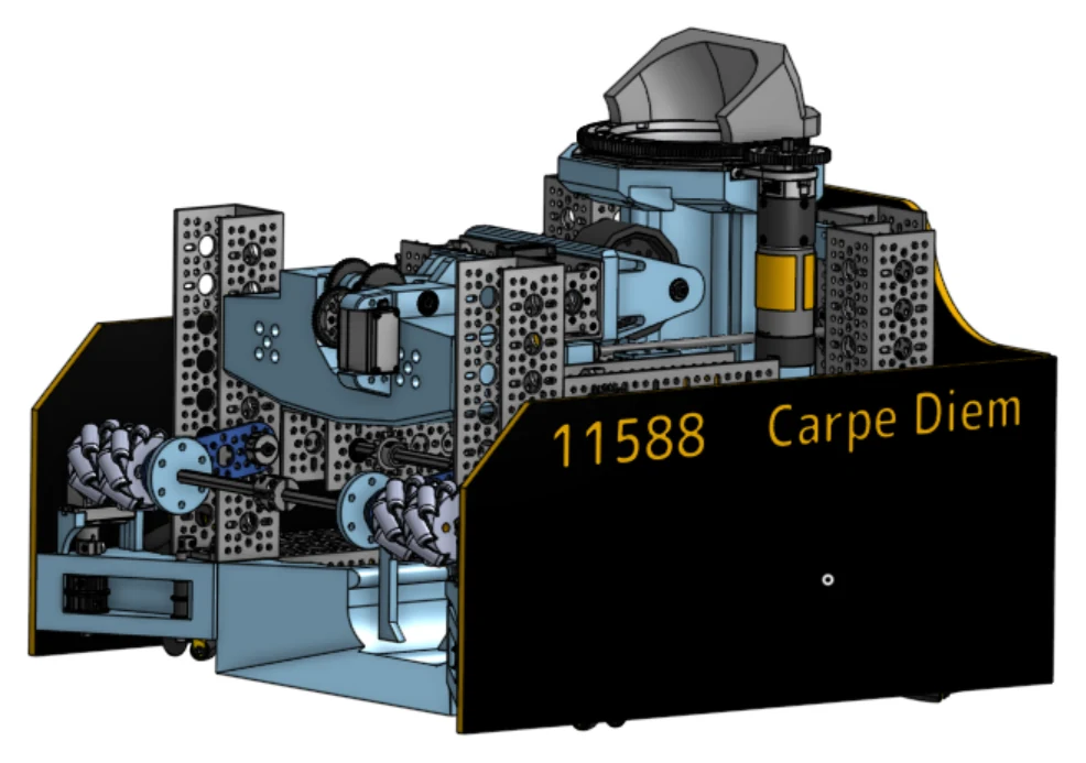
Three seasons on a FIRST Tech Challenge team, from builder to build captain and co-captain. I lead the build team and have defined and built the drivebase every season. The team has earned the Inspire, Think and Motivate awards and competed at the North Carolina Championship.
- 2024–25
- Builder; Build Captain from spring 2025
- 2025–26
- Build Captain
- 2026–27
- Build Captain and Co-Captain
- Time
- About 7 hours a week, year-round
- Team
- Team project; awards are team awards
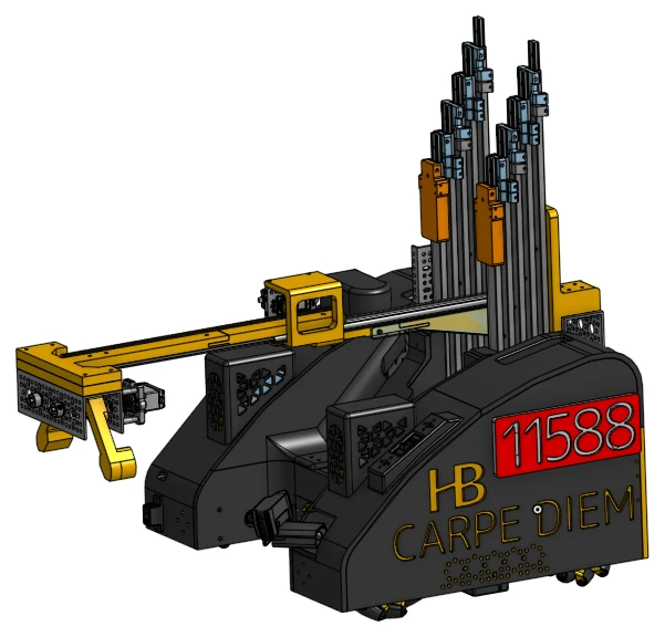
Team results
| Season | Event | Result |
|---|---|---|
| 2025–26 DECODE | Qualifying tournamentJanuary 17, 2026 | Inspire Award. Finalist alliance. First in advancement points, qualifying for the NC Championship. |
| 2025–26 DECODE | North Carolina ChampionshipFebruary 2026 | Competed at the state championship. |
| 2024–25 INTO THE DEEP | Thales Academy Rolesville qualifierJanuary 18, 2025 | Think Award, 2nd place. |
| 2024–25 INTO THE DEEP | Emerging Technology Institute qualifierFebruary 8, 2025 | Motivate Award. |
Official records: 2025–26 season and 2024–25 season.
Leading the build team
The team has three captains: build, programming and outreach. I was made build captain in spring 2025, during my first season, and took on co-captain as well in 2026–27.
- I instruct the builders and keep design discussions moving.
- I run the design process, approving or vetoing mechanism designs and pushing the good ones forward.
- I define the drivebase requirements and build the drivebase. I've done it in all three seasons.
I also wrote the team's 12-slide hardware training deck: structure, shafts and bearings, motors, gear ratios, drivetrains, electronics wiring and common failure modes.
BIOBUZZ, 2026–27
Role: Build Captain and Co-Captain
My biggest season so far, and the one with the most independent work. The robot takes game pieces in through an intake, passes them through a paddle transfer and scores them with an adjustable launcher on a rotating turret.
- My designs: the overall robot layout, the drivebase, the side plates, the complete paddle transfer system, and a camera mount that pans 360° and tilts. That's about 150 hours of Onshape CAD as of November 2026.
- Intake: the concept came from a teammate. I built it and added belts to the intake wedges so they work as conveyors.
- Launcher: a shared mechanism that I contributed to substantially.
The robot is still being built. Competition results go here once it has competed.
DECODE, 2025–26
Role: Build Captain
The robot picked up balls with an intake, sorted them in a vertical spindexer and fired them in the order the game's pattern called for, using a camera and a color sensor. I was one of the core builders of the whole robot.
- Drivebase: I built it myself, a mecanum drive with all four motors inside the frame channels. As far as I know it was a first for the team; earlier robots had some or all of their drive motors sticking up. It freed a clean, flat deck for the ball-handling systems.
- Spindexer transfer: my biggest solo part of the robot.
- Intake: a coach salvaged the spindles from a broken skid-steer street-sweeper brush. I helped work out how to use them as the intake and built their mounts.
Fixing jams at the launcher
The spindexer kept getting stuck on balls and couldn't control when one went into the launcher. The team added a gate that rises to hold the balls while the spindexer selects one, then drops like a drawbridge so the ball rolls over it into the launcher. The gate wasn't my design; I helped implement and build it. It ended the jams and the uncontrolled launches.
The team won the Inspire Award at its January qualifier, was on the finalist alliance and competed at the North Carolina Championship.
INTO THE DEEP, 2024–25
Role: Builder; Build Captain from spring 2025
My first season. The robot used vertical linear slides, a one-stage horizontal slide and a claw that picked up samples and either scored them in the baskets or clipped them onto the rail as specimens. I did CAD all season: I designed the vertical slides and the drivebase, fabricated the side plates and later reworked the claw.
- Claw: it kept breaking. I redesigned its shape and stopped driving it directly off the servo, which ended the breaks.
- Slides: they failed from string tension and overload. I moved the rigging from string to Kevlar to steel cable.
The team won the Think Award (2nd place) and the Motivate Award. I was made build captain that spring and helped prepare the team for the next season.
Outreach
- Astronomy Days, NC Museum of Natural Sciences (February 2025 and 2026): I staff both full days of the team's exhibit, where kids drive six robots across a giant Moon and Mars map. I keep the team's older VEX robots running, coach young drivers and demo the FTC robot on a full competition field.
- Summer robotics camp (2025 and 2026): mentor for rising 6th–9th graders building and programming robots from kits.
- School events: main student presenter for the engineering program at the fall 2026 open house, plus a welcome day for new students and a spring STEM showcase.